|
|
|
|
|
User Manual |
|
Model: AlarmPro-AP-RV1 |
|
Version: 1.0 Date: 25.2.2019 г. |

Copyright Notices
WiseHome’s name, logo and graphics files that represent the Software and the Hardware shall not be used in any way to promote third-party products. The Developer retains sole and exclusive ownership of all rights, title and interest in and to the Software and the Hardware and all Intellectual Property rights relating thereto.
Copyright law and international copyright treaty provisions protect all parts of the Software, products and services. Unless you have a different license agreement signed by (“the Developer”), NO program, code, part, image, audio sample, or text may be copied or used in any way by the user except as intended within the bounds of the single user program. All rights not expressly granted hereunder are reserved for the Developer.
Website: http://www.wisehome.app
CONTENTS
Who is this Manual Written for?
Power on the Device for the First Time
Final checklist before power up
AP-STA mode (Access Point - Station)
Access to Device for Initial Configuration
Event Logging and Notifications Server
Dashboard with registered devices
User Profile notification list
Diagnostics and Troubleshooting
Internet connection reliability
Preface – About this Manual
This manual is intended as a guide to the use of device model AlarmPro-AP-RV1. Please be sure to read the instructions in this manual carefully before operating with the device. The manual is designed to teach you how to mount, connect and configure the device and will prevent you from encountering many problems in the process of using the device.
The information provided in this manual may be changed without prior by the manufacturer notice. You can find the latest version of this manual on the web application provided by the manufacturer. Despite the fact that the manufacturer does not guarantee the accuracy of content, the manufacturer has made every necessary and diligent effort to assure accurate content. All statements, information and recommendations in this document do not constitute any warranty, express or implied. The users are required to take full responsibility upon using the product.
Who is this Manual Written for?
This manual is intended to be used by end users and/or technicians who will mount and configure the device.
Basic knowledge of electrical engineering is required to mount and connect the device safely. Basic computer knowledge is required to correctly configure and operate with the device.
Conventions
· Notes: the notes give recommendations or suggestions, which can help make your work with the device easier and ensure your safety.
· Menu > Submenu > Submenu > Tab - illustrates the menu structure.
· Bold text can mean a menu, menu item, submenu, icon, tool, note, table, name of a button or a field.
Additional Information
· Depending on the device, the latest version of its specific manual, documentation, system software(firmware), application or application tools related to the device‘s operation can be found here: http://www.wisehome.app.
· Device Specifications can be found in the „Specification“ section of this document or here: http://www.wisehome.app.
· Technical support is available here: http://www.wisehome.app/support.
Part 1
Device
Description
The device AlarmPro-AP-RV1 is designed to be used as a remote control, for monitoring and notification. The device can be controlled remotely over the internet by using a computer or a smart phone (phone, tablet). The data produced in the process of monitoring is saved on a cloud server and used for notifications if configured by the user.
Monitoring the logging events requires the device to be added to a registered user profile on the web application: http://www.wisehome.app.
The notifications are only available if the user has been registered and has registered at least one device on the cloud server. Possible ways to get notified:
· If Internet access is available – using the specialized application available on Google Play Store and App Store
· If Internet access is unavailable, but mobile phone network is available – text / SMS. This type of notification requires the purchase of packet of text / SMS messages from within the web application. For more information you can visit the link below: http://www.wisehome.app/sms_gateway
Note: to be able to successfully receive notifications over the internet on your mobile device it is required to have Internet access on that specific mobile device – Mobile Data or Wi-Fi.
Specification
|
Parameter |
Value |
|
Supply voltage |
10 – 15V |
|
Peak current |
350mA |
|
Standby current (relays off) |
~ 80mA |
|
Standby current (relays on) |
~ 220mA |
|
Inputs |
2 |
|
Input activation threshold |
Low, 0V |
|
Max input voltage |
10 - 15V |
|
Minimum length of input signal |
50ms |
|
Outputs |
2 |
|
Maximum load per output |
5A / output |
|
Communication protocol |
IEEE802.11b/g/n |
|
Frequency range |
2412 – 2472MHz |
|
Reception sensitivity |
802.11 b: -91 dbm (11 Mbps) 802.11 g: -75 dbm (54 Mbps) 802.11 n: -72 dbm (MCS7) |
|
Transmit power |
802.11 b: +20 dbm 802.11 g: +17 dbm 802.11 n: +14 dbm |
|
Antenna |
Internal |
|
Buttons |
1, multifunctional |
|
WiFi modes |
AP, STA+AP, STA |
|
Security |
WPA, WPA2 |
|
Encryption |
WEP, TKIP, AES |
|
Network protocols |
IPv4, TCP/IP |
|
DHCP |
Client, Server |
|
WiFi certification |
CE, TELEC, WiFi Alliance, SRRC |
Part 2
Installation
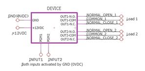
Wiring Diagram
Device is designed to use external power supply. The power supply should provide power 8 - 15V / 500mA.
Generic wiring diagram:
|
|
|
Wiring to interact with an alarm:
|
|
|
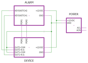
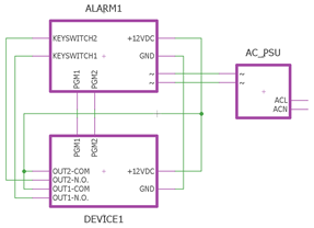
Note: If the same power supply is being used for other devices, make sure that the additional power consumption of the device will not exceed its operating parameters!
Mounting
Given the fact that the device communicates over a wireless network, it must be installed away from electromagnetic radiation sources (such as transformers, pulse power modules, high voltage cables, permanent magnets, etc.) and away from massive metallic objects to ensure a stable connection.
The device is attached to a flat and clean surface with the mount tape provided with the product.
Part 3
Configuration
Power on the Device for the First Time
Final checklist before power up
Before turning on the power supply check if the device has been mounted and connected correctly!
Connect the power supply
The device is designed for uninterrupted mode of operation. To prevent the device from being easily disconnected negligently or maliciously, a power switch is not provided. The power supply should be controlled by the existing external power module.
Operating Modes
AP mode (Access Point)
This is the mode in which each new device or any device on which the factory settings have been restored after a “factory reset”. The device acts as an access point and creates a wireless network with a name of the "SmartHome XXXXXX" type, where XXXXXX is the serial number of the device.
AP-STA mode (Access Point - Station)
The device is in this mode when it has already scanned for wireless networks, but is not yet connected to any of them.
STA mode (Station)
This is the mode in which each configured and connected to a wireless network device works. The device is configured as a wireless client and is no longer visible on the wireless network list. The device receives an IP address automatically via DHCP from the router (that manages this wireless network) and accesses the Internet through it.
Access to Device for Initial Configuration
To access the device in its AP and AP-STA mode, you need a computer or smart device with a wireless network with up-to-date browser (such as IE, Mozilla Firefox, Google Chrome, or any compatible). Turn on the device and open the list of wireless networks on your computer or smart device:
![]()
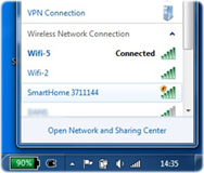
Select the devices wireless network "SmartHome XXXXXX" and click Connect. After successful connection, open a web browser and connect to http://192.168.200.1. You will see this panel:
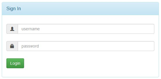
Enter user name and password to gain access to the device. Default user:
· User name: admin
· Password: admin
Note: Attention! Username and password are case-sensitive.
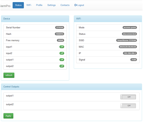
After successful login with the correct username and password you will see this panel:
Menus

1. Main menu – contains submenus: Status, WiFi, Profile, Settings, Contacts, Logout.
1.1. Submenu WiFi – contains the wireless settings.
In order for the device to be able to communicate with the management and monitoring server, it must have access to the Internet. Connect the device to a wireless network:
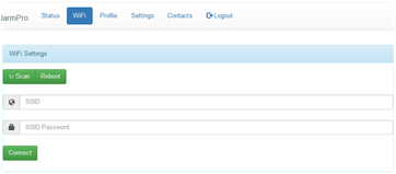
· You can enter the wireless networks’ name and password manually.
· You can click the Scan button and the device will automatically scan for wireless networks. Select the desired network from the list. In the SSID Password
As a final step in the connection procedure, click the Connect button.
1.2. Submenu Profile – from here you can change the username and password used to access the device.
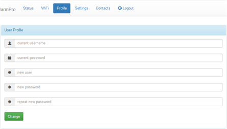
Note: You need to remember your current username and password to change your username and password. In case you have forgotten them, you must reset your device to factory settings and reconfigure it.
In
the field with icon ![]() enter your current username
enter your current username
In
the field with icon ![]() enter your current password
enter your current password
In three fields with icon ![]() enter your
new username,
new password, repeat your new password in their respective fields.
enter your
new username,
new password, repeat your new password in their respective fields.
To confirm your changes press the button Change.
1.3. Submenu Settings – from this menu you manage the settings of the device.
Input settings:
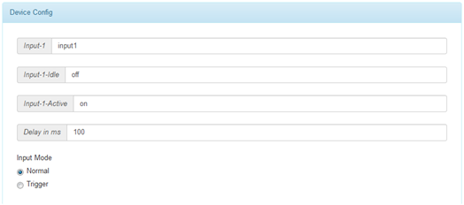
The field values of Input-X, Input-X-Idle, Input-X-Active will be saved on the server and used across all the applications to remind you of the input's functionality.
Input-X – with default value of inputX, where X is the sequential input number. The purpose of this field is to remind you of what the specific Input-X functions as.
Input-X-Idle – with default value of off, where X is the sequential input number. The purpose of this field is to name the idle state of the respective Input-X. In Normal mode the input will change to this state when the PGMX input (e.g. for Input-1 - PGM1) is being supplied with voltage of 8-15VDC. In Trigger mode the input will swap to this state from Input-X-Active state upon receiving an impulse on the PGMX input.
Input-X-Active – with default value of on, where X is the sequential input number. The purpose of this field is to name the active state of the respective Input-X. In Normal mode the input will change to this state when the PGMX input (e.g. for Input-1 - PGM1) is being supplied with voltage of 0VDC. In Trigger mode the input will swap to this state from Input-X-Idle state upon receiving an impulse on the PGMX input.
Delay in ms – with default value of 100ms, the field indicates the pulse duration at which the input will detect a logical level change in milliseconds - used for interference prevention.
Input modes – determinate how the respective input would function:
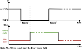
· Normal - the input state of the Input-X changes as the PGMX input voltage changes with a delay - Delay in ms.
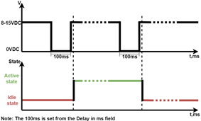
· Trigger – the Input-X swaps between states when PGMX input receives an impulse of 0VDC with a delay - Delay in ms.
|
Normal mode |
Trigger mode |
|
|
|
Output settings:
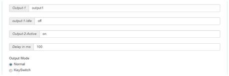
The field values of Output-X, Output -X-Idle, Output -X-Active will be saved on the server and used across all the applications to remind you of the output's functionality.
Output-X – with default value of outputX, where X is the sequential output number. The purpose of this field is to remind you of what the specific Output-X functions as.
Output-X-Idle – with default value of off, where X is the sequential output number. The purpose of this field is to name the idle state of the respective Output-X. In Normal mode the output will change to this state when a command event to turn off is received. In KeySwitch mode the output will stay in this state indefinitely until a trigger command is received.
Output-X-Active with default value of on, where X is the sequential output number. The purpose of this field is to name the active state of the respective Output-X. In Normal mode the output will change to this state when a command event to turn on the output is received. While in KeySwitch mode it is only changes to this state for Delay of ms.
Output relay contact states:
|
Relay Contact |
OFF |
ON |
|
Normal open (N.O.) |
off |
on |
|
Normal close (N.C.) |
on |
off |
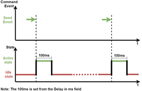
Delay in ms – with default value of 100ms, the duration of the output pulse. Used only for KeySwitch mode.
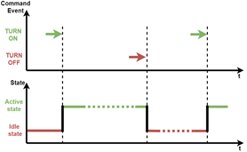
Output mode – determinate how the respective output would function.
· Normal – received command event will change the current state indefinitely until a command to swap the current state of the output is received.
· KeySwitch – the output is turned on for a specific amount of time in ms - Delay in ms.
|
Normal mode |
KeySwitch mode |
|
|
|
NTP and Time zone settings:
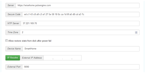
Server – field is filled with the monitoring server of the device. It should not be changed unless a personal SaaS service is used.
Secure Code – certificate password for the monitoring server.
NTP Server – server used to automatically set the clock on the device.
Time Zone – time zone in which the device is located.
Note: If a wrong time zone is set, the events will not be logged on the server correctly.
Allow restore state from disk after power fail – Saves the states of the outputs at power failure. If this box is checked, once the power is restored, the states of the outputs will also recover.
Device Name – field is used to change the name of the device.
To confirm the changes in the submenu Settings click the button Change.
1.4. Submenu Contact – contact information for the company.
1.5. Submenu Logout – logout from the device.
Note: When the button Logout is clicked the session to the device ends without warning!
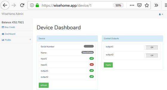
2. Section Device
· Serial Number – serial number of the device.
· Hash – system verification value for the device.
· Free Memory – free memory of the device.
· InputX (х is the sequential number of the respective input) – shows the state of the input.
· OutputX (х is the sequential number of the respective output) – shows the state of the output.
· Button Refresh - used to manually refresh the data.
3. Section WiFi
· Mode – shows the current operation mode of the device
· Status – device connection to the server status
· SSID – name of the current wireless network
· MAC – MAC address of the device
· IP – current IP address
· Signal – Signal Strength of the current wireless network
4. Section Control Outputs – manual control of the output states of the device. Functionality of each output is set from the Settings menu.
Click the button of the corresponding output, which you want to manage. To confirm the changes and send the request click the Apply button.
Note: You can manage more than one output simultaneously.
Configuration Steps
To configure a new device or to reconfigure a device after factory reset, follow these steps:
Note: Before you proceed with the configuration steps, you must read the “Access to Device for Initial Configuration” and “Menu Content” sections in order to prevent potential mistakes!
1. Connect the computer/smartphone/tablet to the wireless network of the non-configured device.
2. Log in the device with the default username and password.
3. Go to the WiFi menu and enter the credentials (SSID and password) for the wireless network that the device will operate with. Click the button Connect to confirm. The device will attempt to connect to the desired wireless network using your credentials. During this attempt you should see load information about the connection process.
3.1. If the connection has failed – make sure your credentials (SSID and password) are correct and try again.
3.2. On successful connection your browser’s URL change to the new IP address. If your computer/smartphone/tablet do not connect automatically to this wireless network your browser informs you that there is no connection. In this case manually connect to this wireless network, that you just connected the device to and refresh the page.
Note: If for any reason the connection was unsuccessful you will be returned back to the WiFi menu.
4. Log in the device again
5. In the Settings menu, set the functionality of the inputs and outputs.
6. Set your time zone.
7. Confirm the settings.
8. Double-check that device registers events and executes commands by activating inputs and outputs manually.
9. To be able to receive notifications on a smartphone please refer to the sections of this manual related to the notification server and mobile application.
10.
Part 4
Event Logging and Notifications Server
Purpose
Accepts and stores events from devices and sends notifications to a smartphone over the Internet and/or by SMS.
Registration
To use the device to its full potential you need to follow these steps:
1. Create a profile for the Event Logs and Notifications
2. Download and install on a smartphone/tablet the specialized application to receive notifications.
3. Register the device/devices on your profile.
![]() To register a profile, start a web
browser (an up-to-date browser such as IE, Mozilla Firefox, Google Chrome, or any
compatible) and open connection to https://wisehome.app/
To register a profile, start a web
browser (an up-to-date browser such as IE, Mozilla Firefox, Google Chrome, or any
compatible) and open connection to https://wisehome.app/
On a mobile device:


Fill in your details in the registration form:
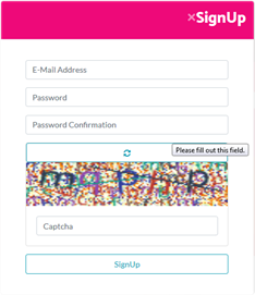
Note: All fields are required! The data you fill out will be used only for the purpose of communication with the used services provided by us and will not be forwarded to any third party.
E-Mail Address: The e-mail address must be valid and you must have access to it. Unless you are able to verify your e-mail address you will not be able to activate your User Profile.
Password: The password must be at least 6 characters long.
Password Confirmation: Enter the password again for confirmation.
Captcha:
series of colored characters. If you are having trouble with reading the
characters – you can generate a new sequence by clicking the reset button![]()
When you are done with entering the details click on the Signup button.
You will receive a confirmation message at the e-mail address you have provided. Click the confirmation link in the message to complete the activation process.
Login/Logout
To Log in your user profile click the button ![]()
![]()
On mobile device:

Enter your profile credentials and click the Login button to confirm.
Note: Make sure you the caps lock key is not on and that you are using the correct case for each letter in your username and password.
Upon successful login you will see:
1. Dashboard menu, if you have registered more than one device on your profile.
2. Device Dashboard menu, if you have registered only one device.
3. Profile > Manage Devices submenu, if you have not registered any devices yet.
Dashboard Menu:

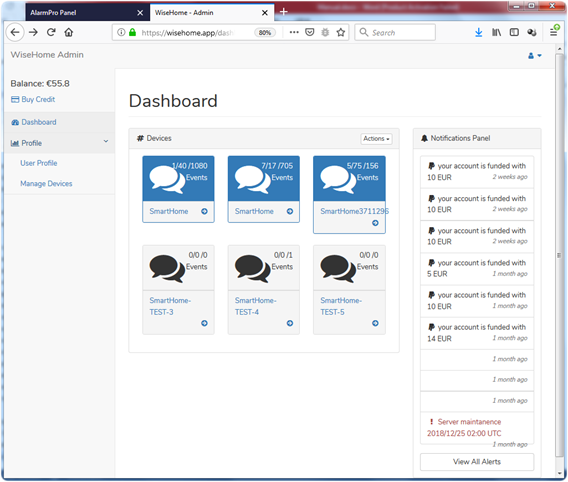
1. Main menu
2. Dashboard with registered devices
3. User Profile notification list
4. User Profile management menu
Main menu
Contains links to access Dashboard with registered devices, user profile, devices management and SMS credit panel.
Dashboard with registered devices
Lists all devices, which are registered with this user profile and gives access to information fir them and actions with them – add new device, delete existing, etc.
· Monitoring inputs and managing outputs
· Viewing events
· Notification management
· Add/Remove device
Monitoring inputs and managing outputs – as it’s described in section Menus, paragraph 2 and 4.
Event history
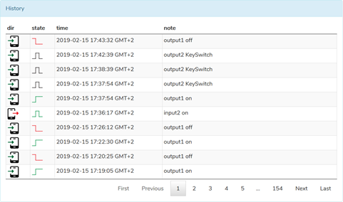
Each event is described with direction, state, time and note.
1.
Direction – shows whether the device received a
command to manage the outputs (noted in the list with icon ![]() ) or registered change in the state of inputs and sent this
event to the server (noted with
) or registered change in the state of inputs and sent this
event to the server (noted with ![]() ).
).
2. State - in dependency of whether it’s for input or output depictions are:
2.1.
Activated output in Normal mode - ![]() ,
задействан изход в режим KeySwitch -
,
задействан изход в режим KeySwitch - ![]() .
.
2.2.
Deactivated output - ![]() .
.
2.3.
Activated input in Normal mode - ![]() ,
activated input in Trigger mode -
,
activated input in Trigger mode - ![]() .
.
2.4.
Deactivated input - ![]() .
.
3. Time – when the event is happened according to the settings for time zone in the corresponding device.
4. Description – short text description of the event.
Notification management


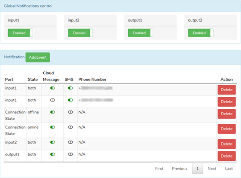
It is split in 2 parts - Global notification control (per every input and output) and Notification (creating events)
1. Global notification enables or disables notification events for corresponding input or output if any are defined in the notification table. To enable/disable notification for corresponding input or output click the button below it.
2. Notification – define under which conditions what notification type will be sent. Available notification types are Cloud Message (over the Internet) and SMS. To create new notification click Add Event button:
2.1. Port – for which input, output or device state to notify:
- InputX – name of corresponding input as it is set in the device
- OutputX – name of corresponding output as it is set in the device
- Connection State – state of connection to the Internet
2.2. State – for which type of change to notify:
- On – when corresponding input/output is activated
- Off – when corresponding input/output is deactivated
- offline – when connection to the Internet is lost, online – when connection is recovered
2.3. Cloud Message – to send or not message over the Internet
2.4. SMS – to send or not SMS (paid service, to use it you need to buy SMS credit)
2.5. Phone Number – cellphone number to send SMS to. Necessary only when SMS notification is selected.
Note: To receive notifications over the Internet you need to have smartphone with WiseHomeApp application installed.
Add/Remove Device
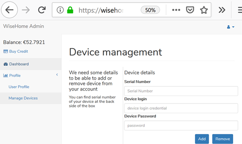
To add or remove device it is necessary to have:
· It’s Serial Number
· It’s Device Login (user name) and Device Password.
Fill in these fields and click Add button to add a device, or Remove button to delete it.
Note: If you forget the username and/or password to a device registered in your profile you can use Factory reset procedure and remove it with its default user name and password.
User Profile notification list
Important events to the user profile are listed here – e.g. when SMS credit was purchased, pending server maintenance, etc.
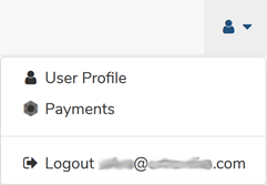
User Profile management menu
It’s intended for Login/Logout, profile settings management and access to SMS credit purchase section.
User profile – настройки на потребителския профил.
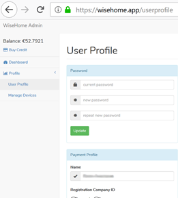
1. Password section – User profile password change.
Note: All fields in this sections are mandatory!
2. Payment profile section – payment processing data when purchasing SMS credit is entered here.
|
|
|
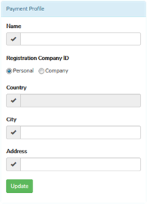
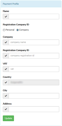
For personal profile mandatory fields are Name, Country, City and Address. Country is detected by your IP address from which you opened connection to www.wisehome.app.
For company profile mandatory fields are all without the VAT field. If the company is established in a country which is member of European Union just enter its Company Registration ID and all necessary data will be extracted from the VIES and filed in automatically. If the company is not established in EU data should be filled in manually. Country is detected by your IP address from which you opened connection to www.wisehome.app.
SMS credit
The SMS notification is useful in cases when you need to be notified on non-smart device, do not have Internet access, or your Internet access service is unreliable and user cannot receive notifications over the Internet. For the notification by SMS to be able to function you need to buy SMS credit.
Note: Before proceeding to buy SMS credit please fill in all necessary data in Payment Profile section in your user profile. This data will be used to process your payments.
Note: The field Country is detected by your IP address from which you opened connection to www.wisehome.app. It cannot be changed manually.
The whole process consists of 3 steps:
1. Select the amount of money for SMS credit (minimum possible amount is 2€ )
2. Preview of Invoice data
3. Preview of payment amount
To complete the process klick Pay button.
Note: We accept PayPal and wire transfer. If you wish to pay with wire transfer please contact Support center.
Step 1 – to buy SMS credit click Buy Credit from the main menu:
![]()
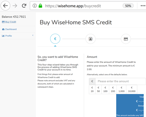
Here you should enter the amount for SMS credit - manually (minimal amount 2€) or by one of the presets.
Note: If you choose to pay 50€ or more you will get bonus (noted in Bonus field).
After selecting desired amount confirm with Save and Continue button.
Step 2 – Here you can review the Invoice data, as filled in the user profile:
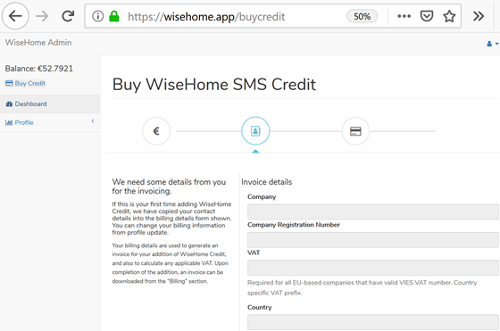
Review the Invoice data and confirm with Save and Continue.
Step 3 – review the payment data and confirm with Pay.
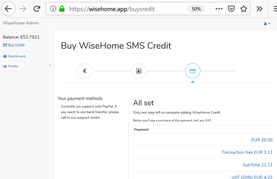
You
will be redirected to PayPal website to finish the payment.
Part 5
Diagnostics and Troubleshooting
Diagnostic methods
If the device does not operate or does not operate correctly, use the following diagnostic methods BEFORE contacting technical support.
Internet connection reliability
On a computer connected to the same local area network, open a command prompt (or Linux console) and run the command
ping www.wisehome.app
You should see a similar result:
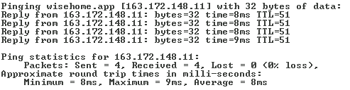
If you notice packet loss (Lost is greater than 0) or too high server response time (time more than 200-300ms) restart your router. In case this does not fix the problem contact your Internet Service Provider (ISP).
Event Logs
The collected event logs in the profile can be used to tract the activity of the device. To check if the device is operating properly:
· Check if the router to which the device is connected has access to the Internet.
· Check the device settings.
· Manually trigger the changes of input and output states.
· Check if the event logs match the order and trigger time.
· If the event logs are delayed, check your Internet connection. If necessary restart your router.
· Check again if the event logs match the order and trigger time.
· If the problem persists restart the device.
· In case the issues are not fixed with any of the diagnostic methods, contact technical support.
Diagnostic LED
The diagnostic LED shows the operation mode of the device and provides guidance in troubleshooting issues with the operation of the device. The signaling is done with a series of light pulses, and after the whole sequence ends there is a pause of 2 seconds.
Pulse Durations:
Ø Fast pulses – pulse duration 0.05 seconds
Ø Slow pulses – pulse duration 1 seconds
Ø ● pulse duration 0.2 seconds
Ø − pulse duration 0.5 seconds
|
Signal |
Meaning |
Troubleshooting Actions |
|
4 fast pulses |
The device is in AP mode. |
Configure your device |
|
1 fast pulse |
Normal mode – the device has finished doing all necessary actions to function and has connected to the server. |
No need to take any action. |
|
1 slow pulse |
The device does not have a valid license. |
Contact technical support. |
|
− − − − |
The device cannot connect to the wireless network. |
1. Check if you can scan and find the SSID of your wireless network in the menu WiFi. 2. Check if you have entered your name and password correctly. 3. Check your Router/AP settings. 4. Restart your Router/AP. Connect your device to the wireless network again. 5. Contact technical support. |
|
● − − − |
The device has connected to the wireless network, but Internet access is not available. |
1. Test your Internet connection. 2. Test your Internet connection on other devices connected to the wireless network. If Yes – restart the device. 3. Check the Router/AP settings. 4. Restart your Router/AP. 5. Contact technical support. |
|
● ● − − |
The device fails to get authorized on the server. |
1. Check your Internet connection reliability. 2. Restart the device 3. Restart the Router/AP. 4. Contact technical support |
|
● ● ● − |
The device has been authorized on the server, but connection has dropped |
1. Check your Internet connection reliability. 2. Restart the Router/AP. 3. Restart the device. 4. Contact technical support. |
Reset Button
The button can be used to do the following:
Reset
Force restart your device – to do that you will need to press the button once and hold for 1 second and then release. The device will restart itself and keep its settings.
Note: Warning! If you accidentally press the button a second time within 2 seconds after a reset command is issued, the device will restore its factory settings!
Wireless settings reset
This procedure is useful in cases when your device was already connected to a wireless network, but this network is non-available or inaccessible anymore (moved to new location, WiFi router damaged, etc.). WiFi access data will be deleted, all other user settings remain. Device will return to AP mode and will be accessible with its last user name and password, ready to be connected to a new wireless network.
1. Press the Reset button, hold it for 1 second and then release.
2. After releasing the Reset button, the diagnostic LED will light up for 2 seconds. During this time window you must click the Reset button again.
Factory reset
To restore factory defaults for a device which is not configured to access wireless network (e.g. it’s in AP or AP+STA modes):
1. Press the Reset button, hold it for 1 second and then release.
2. After releasing the Reset button, the diagnostic LED will light up for 2 seconds. During this time window you must click the Reset button again.
3. Wait until device returns in AP mode and appear in wireless networks list.
4. Press the Reset button, hold it for 1 second and then release.
5. After releasing the Reset button, the diagnostic LED will light up for 2 seconds. During this time window you must click the Reset button again.
Note: Warning! This action will delete all of the user settings – wireless network, the names of the inputs and outputs. The factory settings are restored and the device starts operates in AP mode. To continue using the device, the configuration procedure must be repeated.